

Bolivia Salt Flat is not Flat

The Bolivia Salt Flat
The salar de Uyuni (i.e. the Bolivia Salt Flat) in the Bolivian Andes is the largest salt flat on Earth, exhibiting less than 1 m of vertical relief over an area of 9000 km2. [1]
UNAVCO Reference Stations
UNAVCO is a non-profit university-governed consortium that facilitates geoscience research and education using Geodesy and supports geoscience research around the world.
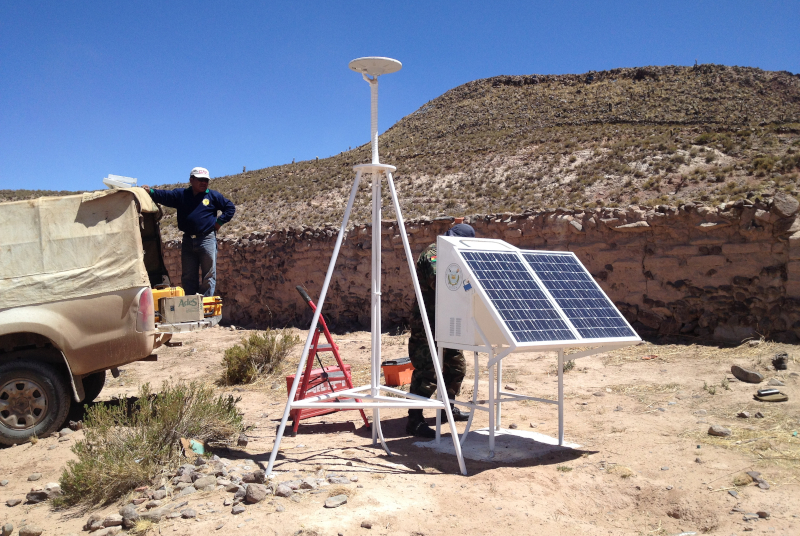
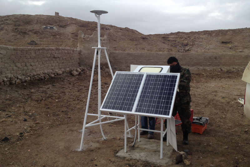
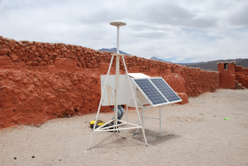
The UNAVCO GAGE Facility manages a community pool of high accuracy portable GPS/GNSS receiver systems that can be used for a range of applications. These complete systems – receivers, antennas, mounts, power and optional communications – can be deployed for days in episodic campaigns or for many months long-term investigations. Systems are also available for precision mapping applications.
This GPS/GNSS reference stations provide their location to sub cm accuracy in Earth Centered Earth Fixed (ECEF) cartesian coordinates. We can use the 3D positions of this stations to measure the curvature drop, or lack of, to find out whether the Salt Flat are as flat as they look, or curve according to the Globe Model.
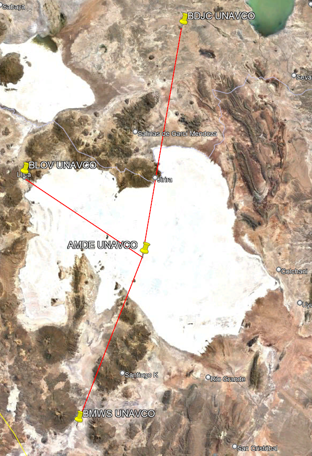
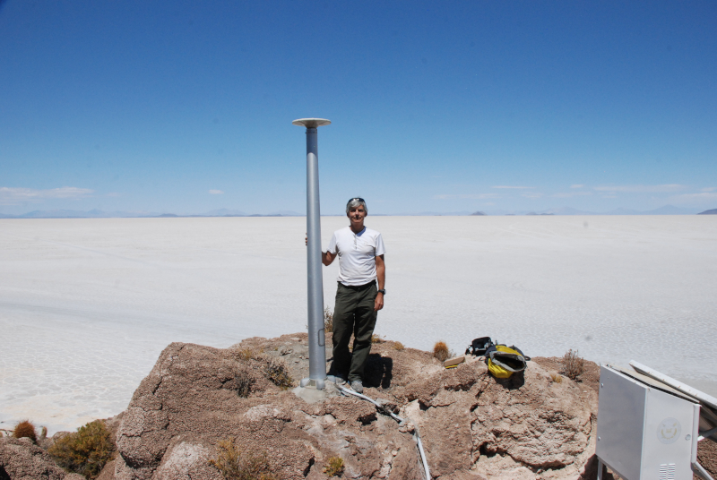
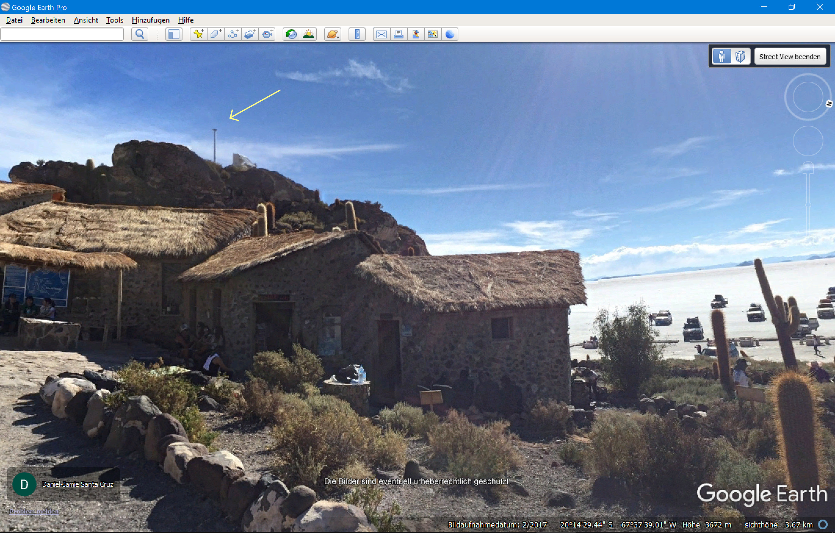
The reference station AMDE is located on the Isla Incahuasi in the middle of the Bolivian Salt Flat. Three more stations, BDJC, BMWS and BLOV, are located around the Salt Flat, see Image.
Reference Station Data
The GPS locations of the following UNAVCO reference stations can be viewed and analyzed in my Geo-Data Visualisation and Calculator App or downloaded in CSV format 2021-11-29 UNAVCO Reference Stations.zip.
| Station | X | Y | Z | Lat/Long | H | ΔH |
|---|---|---|---|---|---|---|
| AMDE | 2280008.627 | -5539233.901 | -2194098.501 | -20.24161900 -67.62740400 | 3715.800 | 0.000 |
| BDJC | 2315256.507 | -5569563.551 | -2078385.509 | -19.13178800 -67.42744100 | 3808.800 | +93.000 |
| BMWS | 2234836.279 | -5523178.606 | -2278862.673 | -21.05930135 -67.97033375 | 3727.091 | +11.291 |
| BLOV | 2225593.314 | -5577206.54 | -2153730.805 | -19.85361900 -68.24544900 | 3735.600 | +19.800 |
All values except Lat/Long are given in meters. H is the ellipsoid height, not the elevation above the Geoid. You can copy the values in the Lat/Long field and paste it in Google Earth to find the corresponding location. Lat/Long/H are calculated from the X,Y,Z coordinates using the WGS84 globe model (see WGS84 Calculator). They are not used for any of the following calculations. They are only provided to find the locations on any map.
You can find the source images by blicking the icon with the question mark below each image. On the UNAVCO website there is also a Directory with the images of other UNAVCO Stations around the Earth.
How to find the Shape of the Earth
X,Y,Z and Lat,Long,H describe exactly the same location in 3D space in 2 different coordinate systems. If the earth is flat, than all locations lie on a flat plane in 3D space, no matter which coordinate system we use. If the earth is a globe, the locations lie all on the surface of a spheroid in any coordinate system. So we can use the 3D X,Y,Z coordinates to find out the shape the points lie on.
Using the X,Y,Z coordinates and vector algebra we can calculate the drop of the stations around the Salt Flat with respect to the station AMDE in the center of the Salt Flat. If the earth is flat then the calcultions will show no drop between the stations. If the earth is a globe, then the drop must match the prediction of the globe model. So lets see what the data leads to.
Drop Measurements and Calculations
The following table shows the drop calculations from the Station AMDE in the middle of the Salt Flat to the other 3 stations:
| Station | Azim | Dist Chord | Dist Surf | REll | REll+H | Drop GPS | Drop + ΔHx | Drop Pred | ΔDrop | ΔDrop% |
|---|---|---|---|---|---|---|---|---|---|---|
| BDJC | 9.72° | 124705.71 | 124707.72 | 6344128.34 | 6347844.14 | 1132.02 | 1225.02 | 1224.94 | 0.08 | 0.007% |
| BMWS | 201.48° | 97382.06 | 97383.01 | 6348083.11 | 6351798.91 | 735.19 | 746.48 | 746.50 | -0.02 | -0.003% |
| BLOV | 304.49° | 77669.01 | 77669.49 | 6369188.35 | 6372904.15 | 453.50 | 473.30 | 473.29 | 0.01 | 0.002% |
The values in the yellow fields are the final Drop calculations from the GPS measurements, all with respect to the reference station AMDE. The values in the green fields are the predicted values for the WGS84 globe model. If the earth were flat, all the values in the yellow fields would be 0.
- Azim
- Azimuth direction of the Station as seen from AMDE. Azim is used to calculate the ellipsoid radius REll along this direction.
- Dist Chord
- Chord distance d from AMDE location R to a point Q below the other station P at the same ellipsoid height as AMDE:
- with and is the unit vector perpendicular to the ellipsoid surface at P. The components of and are the (x,y,z) coordinates of the locations.
- Dist Surf
- Distance s along the surface calculated from Dist Chord :
- with
- REll
- Ellipsoid radius in the direction Azim. The radius of curvature of the WGS84 reference ellipsoid depends on the direction of the measurement.
- REll+H
- Because all stations are at an elevation of 3715.8 m or slightly above, this height has to be added to the ellipsoid radius. This radius is used to calculate the expected Drop Pred.
- Drop GPS
- Drop in reality, calculated by the Geo-Data Visualisation and Calculator App from the GPS data of the stations, using vector algebra.
- Drop + ΔHx
- Because the stations are at slightly higher elevations with respect to the station AMDE, the differences in the elevations have to be added to the measured Drop GPS values to get the effective Drop of each station with respect to the same elevation as the AMDE station. The tilt of the ΔH value at the drop location with respect to the AMDE station is taken into account:
- with , where = Drop GPS, = difference in elevation between 2 stations, = surface distance between 2 stations and .
- Drop Pred
- Expected Drop calculated for an ellipsoid radius :
- ΔDrop, ΔDrop%
- Difference of measured Drop+ΔHx from GPS data to expected Drop Pred, absolute and relative in %.
To correctly predict the Drop for the globe model, we have to know the radius of curvature between the reference stations.
The WGS84 Globe Model describes the earth as an oblate spheroid, the so called Reference Ellipsoid. Contrary to a sphere, an ellipsoid has not only one radius. In fact the radius of curvature depends not only on latitude, but also on the direction it is measured. To get an accurate drop value prediction, we have to use the directional radius between 2 stations, increased by the elevation of the station AMDE. The calculation of the Azim direction and the directional radius is very complicated. I used my WGS84 Distance, Azimuth and Radius Calculator for that.
Result and Conclusion
As we can see, there is a measured Drop Drop+ΔHx between the stations. The Bolivia Salt Flat curves exactly as predicted by the official Globe Model WGS84.
The Bolivian Salt Flat show a Drop in every direction as predicted by the Globe Model. The Earth is NOT FLAT.
Bonneville Salt Flats
There is another salt lake in Utah, the Bonneville Salt Flats. I have the GPS data from a car driving along Rte 80 recording 1274 data points (thanks Jesse). They clearly show the curvature of the earth too. There are even images and videos showing this curvature:
- The Curvature of the Earth – Bonneville Salt Flats; some Videos by Don’t Stop Motion
Here are the GPS coordinates for the two observation points:
- 40°44’24″N 114°05’59″W
- 40°44’41″N 114°06’15″W
At the top of Wendover Blvd, there’s a place to turn out just by the water basin, the time lapse and 2 other videos are from there. Then I climbed up a big hill (Wendover Viewpoint on Google Earth) and that’s where I got the shot that’s more straight on. I believe it’s roughly 900ft higher than the salt bed. ~ David Cook (Don’t Stop Motion)
- Radius of Earth at Great Salt Lake Desert Rte 80 by Walter Bislin:
How the radius of the earth was measured from vectors measured with Differential GPS - The Bonneville Salt Flats – Visible & Measureable Curvature by Bryant Meyers
“In this video I give a very thorough analysis of curvature as seen at the Bonnville Salt flats and lake ponchartrain. This curvature is REAL and CAN be seen with telescopic cameras at the right vantage point. This is not a trick. Curves will stay curves and straight lines, straight lines, so the curvature seen is NOT a trick.”
Calculating the Drop from GPS Data
We can use the GPS (x,y,z) coordinates of 2 reference stations and vector algebra to calculate the drop between the stations. Lets label the AMDE reference station vector and one of the other stations vector .
The vector from to is then simply . The drop x of P with respect to a horizontal plane tangent to the surface at R is the component of projected onto the axis parallel to the up-direction at the position R. We can get the projection using the dot product of 2 vectors:
| (1) |
|
||||||||||||
| where‘ |
|
Note: To get the effective earth curvature drop we have to bring P to the same elevation as R and then use the same equation above:
| (2) | |||||||||||||
| where‘ |
|
References
 Local copy of PDF (info)
The team of Adrian A. Borsa reports on a kinematic Global Positioning System (GPS) survey of a 45-by-54 km area in the eastern salar, conducted in September 2002 to provide ground truth for the Ice Cloud and land Elevation Satellite (ICESat) mission.
https://academic.oup.com/gji/article/172/1/31/2081107

TikTok: tiktok.com/@olegmks
ВКонтакте: vk.com/olegmks
YouTube: youtube.com/c/OlegMKS
Яндекс.Дзен: zen.yandex.ru/olegmks
RuTube: rutube.ru/channel/23320330/